38 electric motor diagram with labels
Electrical Diagrams and Schematics - Inst Tools Types of Electrical Diagrams or Schematics There are three ways to show electrical circuits. They are wiring, schematic, and pictorial diagrams. The two most commonly used are the wiring diagram and the schematic diagram. The uses of these two types of diagrams are compared in Table 1. Basic wiring for motor control - Technical data guide | EEP Basic wiring for motor control - Technical data. They show the relative location of the components. They can be used as a guide when wiring the controller. Figure 1 is a typical wiring diagram for a three-phase magnetic motor starter. Figure 1 - Typical Wiring Diagram.
Explain the construction and working of the ... - Shaalaa.com Draw a neat diagram and label it. Electric motor - Science and Technology 1. Advertisement Remove all ads. Advertisement Remove all ads. Advertisement Remove all ads. Long Answer. Explain the construction and working of the following. Draw a neat diagram and label it. Electric motor.
Electric motor diagram with labels
PDF Electrical Symbols and Line Diagrams - University of Florida A line (ladder) diagram is a diagram that shows the logic of an electrical circuit or system using standard symbols. A line diagram is used to show the relationship between circuits and their components but not the actual location of the components. Line diagrams provide a fast, easy understanding of the connections and use of components. Electric Motor Diagrams A Split Phase Capacitor Start Electric Motor may be defined as a form of split-phase motor having a capacitor connected in series with the auxiliary winding. The auxiliary circuit is opened by the centrifugal switch when the motor reaches 70 to 80 percent of synchronous speed. Also known as a capacitor-start, induction-run motor. The picture shows a basic diagram of an electric motor ... The picture shows a basic diagram of an electric motor. Which labels best complete the diagram? X: Brush Y: Armature Z: Commutator X: Commutator Y: Brush Z: Armature X: Armature Y: Commutator Z: Brush X: Armature Y: Brush Z: Commutator Advertisement Expert-verified answer SerenaBochenek
Electric motor diagram with labels. PDF Understanding Electric Motor Nameplates Figure 2 is a view of the underside of an electric motor. The letters are NEMA standard letters and the actual dimensions for general purpose motors are shown in Table 1. The diameter of the bolt hole of the motor mounting bracket is letter H. The diameter is 1/32 of an in. larger than the bolt used for mounting. Draw a labelled diagram of an electric motor. Explain its ... Label the diagram of electric motor. Name C & D and mention the use of this component. Hard. View solution > On what principle electric motor works? Easy. View solution > Draw a labelled circuit diagram of a simple electric motor and explain its working. In what way these simple electric motors are different from commercial motors? Draw a labeled diagram of an electric motor. Explain its ... Working of electric motor: As shown in the diagram, when a current is passed through the coil PQRS the coil starts rotating anti clockwise because a downward force acts on length PQ and at the same time an upward force acts on RS. Therefore, the coil rotates in anti clockwise direction. Electric Motor Nameplate Details Explained | Electric ... The nameplate shown in Figure 1 indicates the electric motor is rated 1 HP. With a service factor of 1.15, the motor can be overloaded up to 1.15 horsepower. If the motor is operated in the service factor range continuously, it will cause a reduction in motor speed and efficiency, and an increase in the motor's operating temperature.
NCERT Q11 - Draw a labelled diagram of an electric motor ... An electric motor works on the principle that when a rectangular coil is placed in a magnetic field and a current is passed through it, a force acts on the coil which rotates it continuously Working of an electric motor When battery is switched on, current flows through coil AB from A to B, and Magnetic Field is from North to South... Draw a labelled diagram of an electric motor ... - Sarthaks Working of Electric Motor Current in the coil ABCD enters from the source battery through conducting brush X and flows back to the battery through brush Y. The current in arm AB of the coil flows from A to B. In arm CD it flows from C to D, that is, opposite to the direction of current through arm AB. Draw a labelled circuit diagram of a simple electric motor ... A commercial electric motor is one which uses the following (i) An electromagnet in place of permanent magnet. (ii) Large number of turns conducting wire in current carrying coil. (iii) A soft iron core on which the coil is wound. The combination of soft iron core and coil is an armature. It enhances the power of motor. What is an Electric Motor? with the Help of a Labelled ... An electric motor is a device that converts electrical energy into mechanical energy. Diagram: Electric motor Working of an electric motor: An electric motor works on the principle of magnetic effect of electric current.
Electric Motors Symbols - AC/DC, Single Phase / Three ... DC Shunt Motor. It is the symbol used for DC shunt motor whose field winding is connected in parallel to the armature winding. Both windings are connected to a common Direct Current supply. Single Phase Synchronous Motor. This symbol represents a single phase AC synchronous motor. Synchronous motors initially starts as an induction motor but ... Electric motor Diagram | Quizlet Diagramma electric motor Learn with flashcards, games, and more — for free. Motor Connection Diagrams - Electric Motor Warehouse Electric Motor Wire Marking & Connections. For specific Leeson Motor Connections go to their website and input the Leeson catalog # in the "review" box, you will find connection data, dimensions, name plate data, etc. Single Phase Connections: (Three Phase--see below) Single Voltage: Electric Motor Symbols - Electrical Symbols Electric Motor Symbols. Electric motors are electromechanical devices whose function is to transform electrical energy into mechanical energy through electromagnetic interactions. There are other engines (generators) that produce electricity by exploiting the mechanical energy, such as alternators and dynamos.
Electric motor - eAge Tutor
Electric Car Diagram - Car Construction ELECTRIC CAR. Batteries for Electric cars. Hybrid Construction. Battery lifetime. Electric Motors construction. Permanent magnet synchronous motor. Replacing electric car batteries. Electric Car Repair. Types of electric cars.

PDF Typical Electrical Drawing Symbols and Conventions. Basics 6 7.2 kV 3-Line Diagram : Basics 7 4.16 kV 3-Line Diagram : Basics 8 AOV Elementary & Block Diagram : Basics 9 4.16 kV Pump Schematic : Basics 10 480 V Pump Schematic : Basics 11 MOV Schematic (with Block included) Basics 12 12-/208 VAC Panel Diagram : Basics 13 Valve Limit Switch Legend : Basics 14 AOV Schematic (with Block included)

Patent US6288508 - Electric motor for a vehicle having regenerative braking and reverse ...
Three Phase Motor Power & Control Wiring Diagrams Three Phase Motor Connection Star/Delta (Y-Δ) Reverse / Forward with - Timer Power & Control Diagram Starting & Stopping of 3-Phase Motor from more than One Place Power & Control diagrams Control 3-Phase Motor from more than Two buttons - Power & Control Diagrams ON / OFF Three-Phase Motor Connection Power & Control Schematic and Wiring Diagrams

Types Of Electrical Motor And Its Applications In English Pdf, Electric Motor Working and Its ...
Question 11 Draw a labelled diagram of an electric motor ... Question 11 Draw a labelled diagram of an electric motor. Explain its principle and working. What is the function of a split ring in an electric motor? Solution Principle: It works on the principle of the magnetic effect of current. A current-carrying coil rotates in a magnetic field.

Patent US8307928 - System and method for operating an electric motor by limiting performance ...
7 Parts Of Simple Electric Motor And Function - AutoExpose 7. Motor Housing. Simple Motor Parts and their function. 1. Stator / Armature Coil. The stator includes the main components of the electric motor. Because this component will be in direct contact with the performance of the motor. The stator is a static copper winding located around the main axis.

Protean Unveils Production In-Wheel Electric Motor | Electric Vehicle News
Electric Motor - Principle, Working, Diagram - Explained ... Electric Motor consists of Rectangular Coil of Wire ABCD A strong horseshoe magnet (or 2 different magnets ) - If we take 2 magnets, North Pole of first magnet faces South Pole of Other Magnet, as shown in figure... The coil is placed perpendicular to the magnet as shown in figure The ends of coil are connected to split rings - P & Q
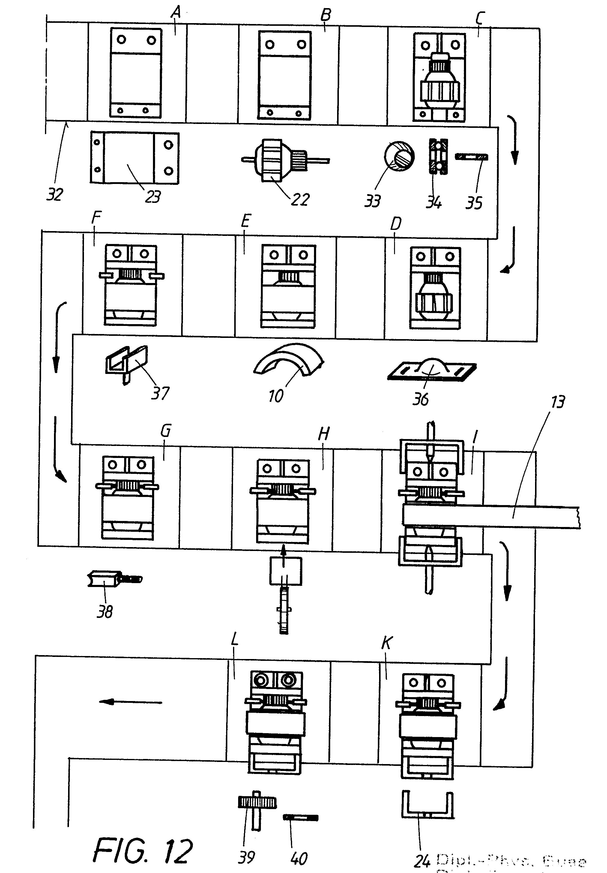
Patent EP0179963A1 - Electric motor for driving apparatuses, in particular household appliances ...
PDF Three-Phase Wiring Diagrams always use wiring diagram supplied on motor nameplate. w2 cj2 ui vi wi w2 cj2 ui vi wi a cow voltage y high voltage z t4 til t12 10 til t4 t5 ali l2 t12 ti-blu t2-wht t3.org t4-yel t5-blk t6-gry t7-pnk t8-red t9-brk red tio-curry tii-grn t12-vlt z t4 til t12 tio til

repair-manuals: 1971-74 Electric Sunroof Repair Manual
Electrical Symbols For Schematic Diagrams | EdrawMax Step 1: Launch EdrawMax on your computer. An extensive collection of electrical diagram templates can be found in the Electrical Engineering category. Click the icon of Basic Electrical to open the library that includes all symbols for making electrical diagrams.. Step 2.1: As you are into the workspace of EdrawMax, drag the symbol that you need directly onto the canvas.

Electrical Engineering World: Starter Motor
Explain the construction and working of ... - OMTEX CLASSES Question 2. Explain the construction and working of the following. Draw a neat diagram and label it. Electric motor. Answer: Electric motor - It converts electrical energy into mechanical energy.. Principle- When a current carrying conductor is placed normally in a magnetic field it experiences a force which rotates the conductor thus mechanical energy is generated.

Hybrid Electric Cars: Parallel Hybrid Electric Vehicle
Electric Motors: How to Read the Nameplate - WorldWide ... By design, electric motors have standard voltages and frequencies at which they operate. On the nameplate, you can see this sample motor is designed to be used on 460 VAC systems. 169.5 amps is the full-load current for this motor. Revolutions Per Minute (RPM) The nameplate includes the based speed given in RPM.

What’s in a motor? - Current E
Electric Motor - Parts of Motor, Working of Electric Motor ... Take two bar magnets and keep the poles facing each other with a small space in between. Now, take a small length of a conducting wire and make a loop. Keep this loop in between the space between the magnets such that it is still within the sphere of influence of the magnets. Now for the last bit. Connect the ends of the loop to battery terminals.

Electric motor - eAge Tutor
The picture shows a basic diagram of an electric motor ... The picture shows a basic diagram of an electric motor. Which labels best complete the diagram? X: Brush Y: Armature Z: Commutator X: Commutator Y: Brush Z: Armature X: Armature Y: Commutator Z: Brush X: Armature Y: Brush Z: Commutator Advertisement Expert-verified answer SerenaBochenek
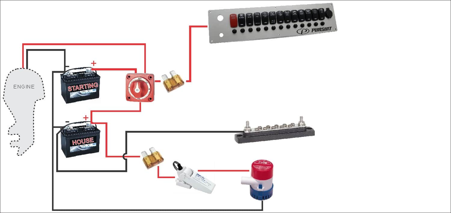
How To Wire A Boat | Beginners Guide With Diagrams | New Wire Marine
Electric Motor Diagrams A Split Phase Capacitor Start Electric Motor may be defined as a form of split-phase motor having a capacitor connected in series with the auxiliary winding. The auxiliary circuit is opened by the centrifugal switch when the motor reaches 70 to 80 percent of synchronous speed. Also known as a capacitor-start, induction-run motor.
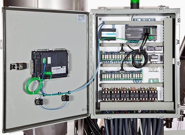
Basic electrical design of a PLC panel (Wiring diagrams) | EEP
PDF Electrical Symbols and Line Diagrams - University of Florida A line (ladder) diagram is a diagram that shows the logic of an electrical circuit or system using standard symbols. A line diagram is used to show the relationship between circuits and their components but not the actual location of the components. Line diagrams provide a fast, easy understanding of the connections and use of components.

Endex treadmill controllers Replacement | Wiring diagram
Post a Comment for "38 electric motor diagram with labels"